The problem coaxial design sets out to solve
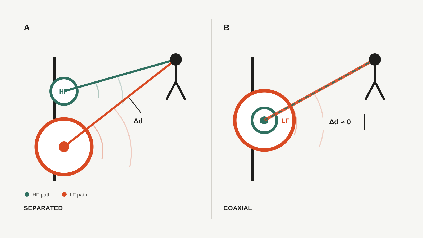
In a conventional two-way loudspeaker, the LF and HF drivers are separated vertically. Around the crossover both drivers radiate the same frequency region, so their sum depends on relative phase and on the difference between their path lengths to the listener. The response can be aligned on axis, yet movement above or below that axis changes the path difference and can produce lobes or cancellations through the crossover region.
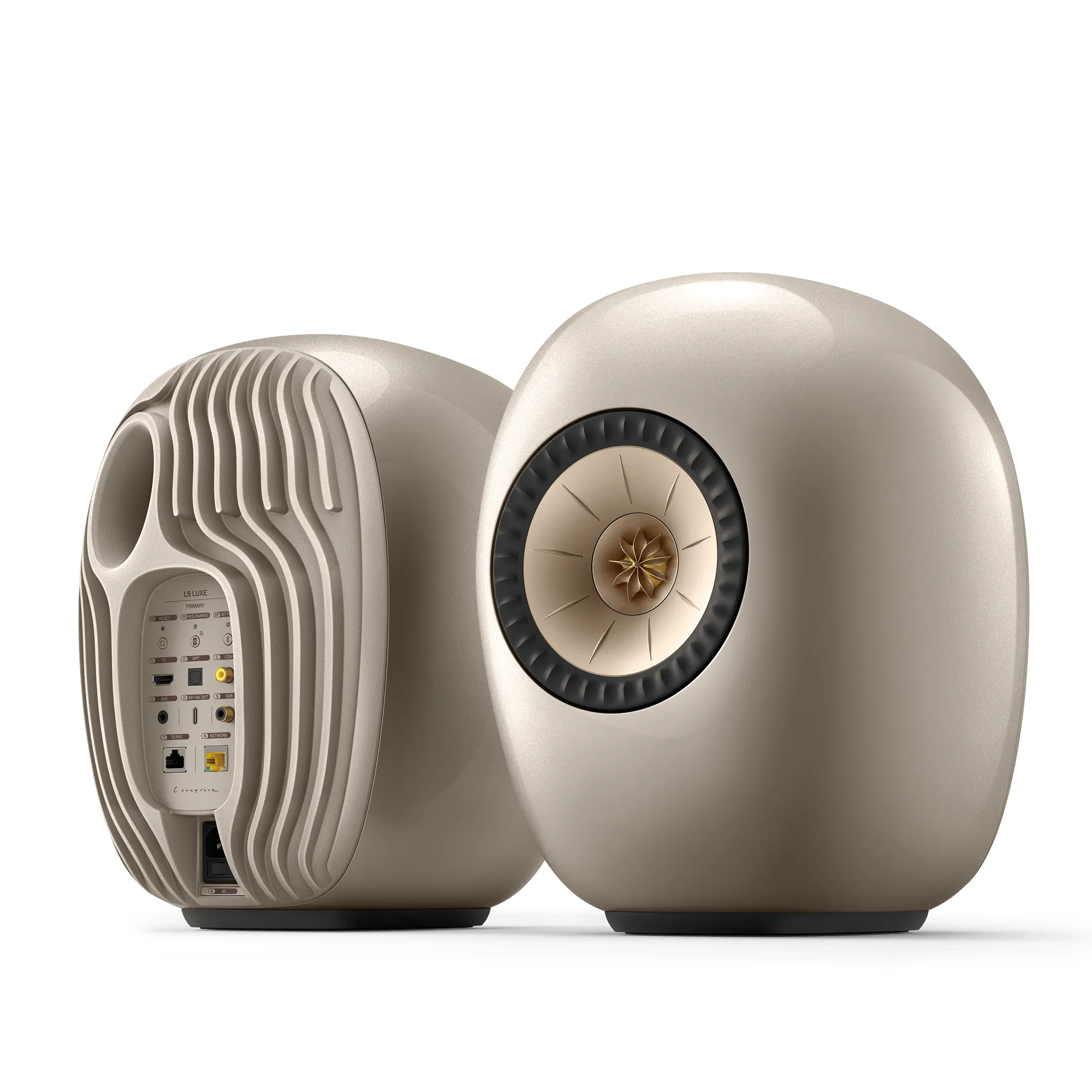
A coaxial assembly places the HF driver at the centre of the LF or MF cone, bringing the radiation axes and apparent source positions closer together. Because listening angle produces less change in relative path length, the crossover sum can remain stable over a wider angular range. The useful result is not merely a smaller baffle: it is a reduction in the way apparent source position changes with frequency.
Joining directivity through the crossover
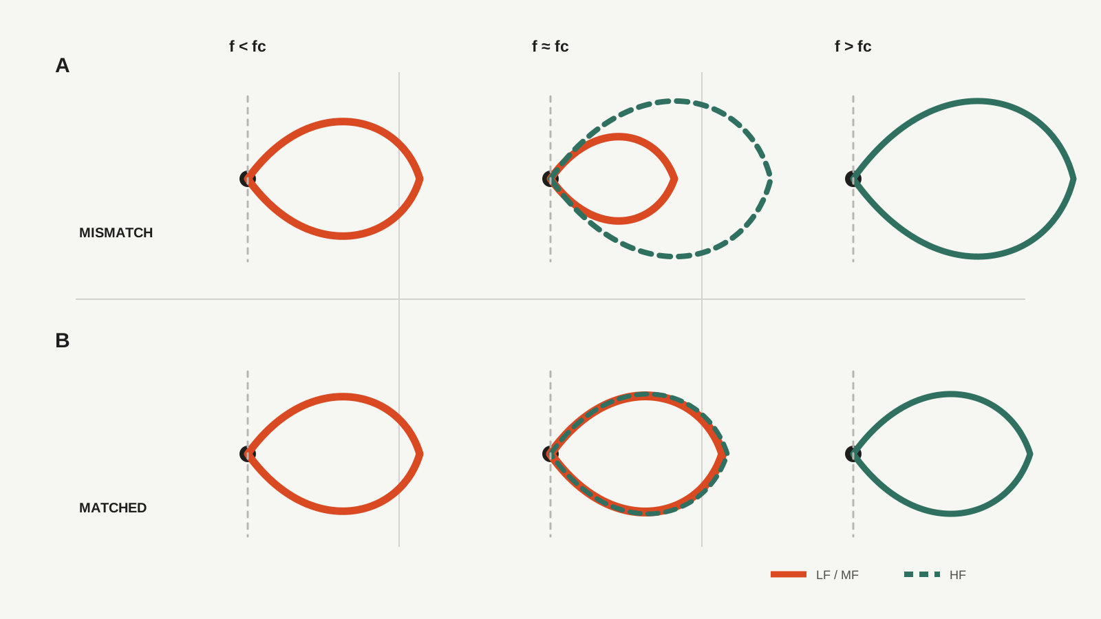
A diaphragm becomes more directional as its size grows relative to wavelength. In a two-way design, the LF cone may already be narrowing as it approaches crossover while a small HF driver would radiate more widely on its own. If that difference is large, the on-axis response may be flat while the off-axis response and total sound power change abruptly around crossover.
Many coaxial drivers use the cone surrounding the HF unit as a waveguide. Shaping the HF radiation towards the directivity of the LF or MF section can produce a smoother off-axis transition through crossover. Width alone is not the objective: whether radiation is wide or narrow, its change with frequency should remain continuous.
That continuity affects reflected energy as well as direct sound. When the listening window stays close to the on-axis response, early-reflection and sound-power curves avoid abrupt changes, and the directivity indices evolve smoothly, the off-axis tonal balance is less likely to shift at crossover.
The crossover does not disappear
A coaxial system still joins two separate moving systems. Their amplitude, phase, acoustic centres and filter slopes must be aligned before the crossover can sum correctly even on axis. Coincident placement reduces the angle-dependent change in path length; it does not automatically correct filter phase rotation or irregularities in the individual drivers.
Crossover frequency therefore cannot be selected from the on-axis response alone. The designer must consider LF or MF directivity, the cone profile guiding the HF output, and phase throughout the overlap region. KEF's Blade/The Reference white paper compares response and directivity index at different crossover frequencies precisely because an electrical dividing point also changes the radiation pattern.
The new difficulties introduced by coaxial construction
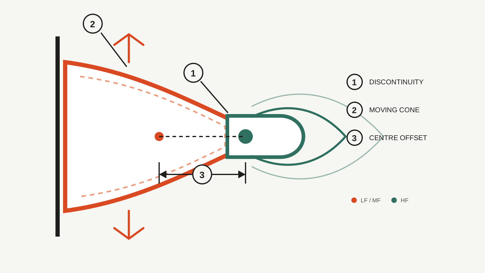
From the HF driver's perspective, the surrounding cone, edge and suspension all form part of the acoustic path. Steps and discontinuities can diffract the wavefront, creating fine irregularities in high-frequency response and directivity. Genelec's MDC joins the cone, suspension and outer waveguide with a smooth profile, while successive KEF Uni-Q generations refine the cone and the region around the HF driver to manage the same coaxial constraint.
In a two-way coaxial driver, the LF cone that acts as the HF waveguide also moves substantially at low frequencies. Large excursion changes the boundary seen by the HF radiation over time and can become a source of modulation and distortion. A three-way coaxial arrangement can reduce this burden by limiting MF excursion and assigning low frequencies to separate drivers.
Nor does a shared visible axis guarantee that both acoustic centres coincide in depth. HF placement, waveguide length, acoustic filtering and electrical delay all affect timing. Coaxial appearance alone is not evidence of a perfect point source or complete time alignment.
Two-way and three-way systems solve different parts of the problem
A two-way coaxial system joins its LF and HF sections on the same axis. Many three-way systems make only the MF and HF sections coaxial and place the LF drivers elsewhere. In that case the coaxial assembly directly solves MF/HF integration, while the LF/MF crossover remains a separate design problem. Driver placement and crossover design can extend the apparent source and directivity behaviour into the low frequencies, but that is an achievement of the complete system rather than of the coaxial driver alone.
What to look for in measurements
Begin with horizontal and vertical off-axis curves around crossover. A flat axial trace is not enough if the angled curves develop deep cancellations or abrupt changes of shape. When those curves retain a similar shape and decay progressively with angle, the two radiating sections are integrating more successfully.
In a Spinorama set, compare the on-axis response with the listening window, examine the shapes of the early-reflection and sound-power curves, and follow the continuity of the directivity indices. Fine high-frequency disturbances should be considered in relation to diffraction around the cone and suspension, resonances in the acoustic path, and the HF driver's own response. The central question is not whether the speaker is coaxial, but how smoothly its radiation remains connected through crossover.
Coaxial design is a method of integration
The central problem addressed by coaxial loudspeakers is the separation of source position and directivity through the crossover region. Sharing an axis provides a strong starting point, but the cone profile, acoustic centres, crossover frequency, filters and diffraction control must still be designed as one system. The meaning of coaxial construction lies not in the visible placement of an HF driver at the centre, but in making multiple radiators behave as one continuous source.